Home > Metal Dome > 4 Leg Cross Shaped Metal Dome Engineering Guide
Technical Sourcing & Engineering Whitepaper

4 Leg Cross Shaped Metal Dome: The Global Hardware Engineer's Guide to Tactile Ratio, Plating Reliability & High-Density SMT Integration

Demystifying trip force calculations, contact resistance stabilization, PCB routing channel optimization, and automated tape-and-reel array manufacturing for mission-critical automotive, medical, and industrial user interfaces.

SUS301 / SUS304 Precision Spring Steel 1M to 5M Actuation Cycles ISO 9001 & SGS Onsite Verified
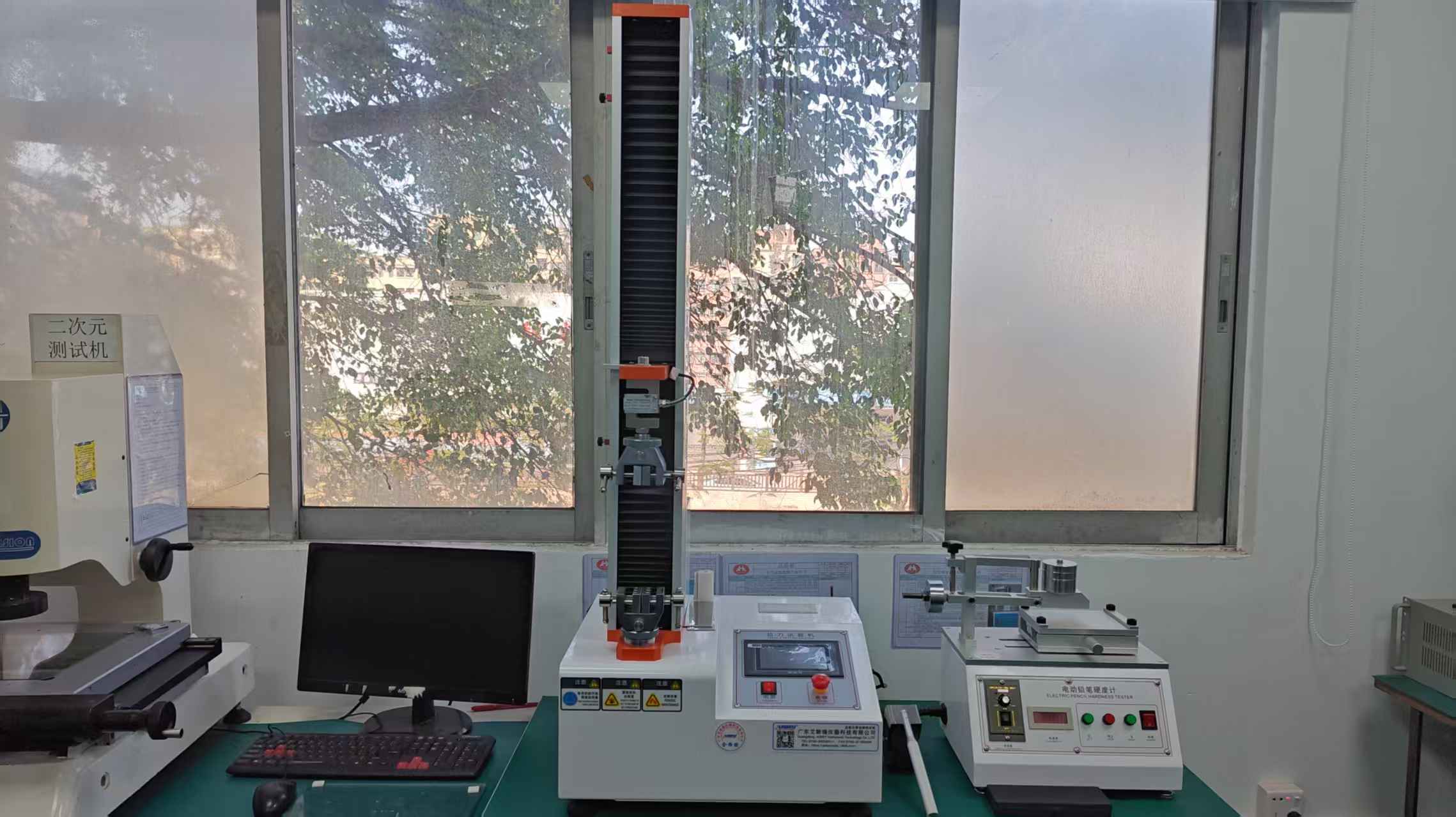
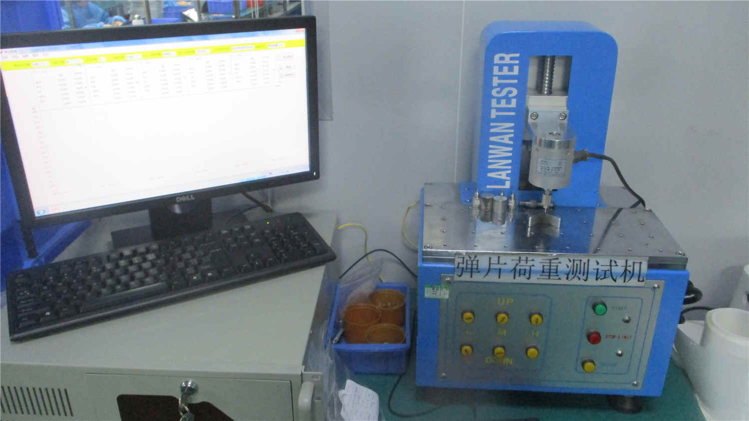
Fragment load tester verifying tactile snap curve of 4 leg cross shaped metal dome at Dongguan Cevra Electronic Technology Co., Ltd.
Precision Quality Validation

In-house Fragment Load Testing of Tactile Ratio (TR%) & Click Snap Force

QC
Authored by HMI Lab
Dongguan Cevra Electronic Technology Co., Ltd.
ISO
Standard Compliance
ISO 9001:2015 & SGS Audited
RoHS
Material Safety
RoHS, REACH & Halogen-Free
DFM
Engineering Review
Instant 24h PCB Stack-up Analysis
Architecture & Kinematics

Engineering Fundamentals of the 4 Leg Cross Shaped Metal Dome

Why modern hardware designers are transitioning from legacy circular snap discs to 4-leg cross architectures for high-reliability human-machine interfaces.

The Mechanics of Crisp Tactility and Space Efficiency

The 4 Leg Cross Shaped Metal Dome (also cataloged in electronic component engineering as the four-legged snap dome, cross tactile dome, or X-dome) represents a pinnacle in mechanical switch contact design. Fabricated from precision cold-rolled Japanese or Swedish stainless spring steel (typically SUS301 high-yield or SUS304 temper), its geometry consists of four distinct radiating legs connected to a spherical apex crown.

When downward vertical actuation force ($F_1$) is exerted onto the central apex—either directly by an external silicone keypad plunger, an embossed graphic overlay, or an ergonomic actuator—the cantilevered legs absorb the bending moment up to a critical threshold known as the Trip Force (or peak snap point). Once crossed, the elastic structure experiences momentary mechanical snap-action bistability, dropping rapidly to the Contact Force ($F_2$).

This rapid delta generates the sharp, audible, tactile "click" prized by human operators. The calculation of this feel is quantified mathematically as:

Tactile Ratio (TR %) = [(Trip Force - Return Force) / Trip Force] × 100%

While round domes typically yield tactile ratios between 20% and 35%, a properly stamped 4 leg cross shaped metal dome achieves tactile ratios ranging from 45% to over 65%, ensuring unmistakable user confirmation even through heavy industrial safety gloves or thick medical-grade protective apparel.
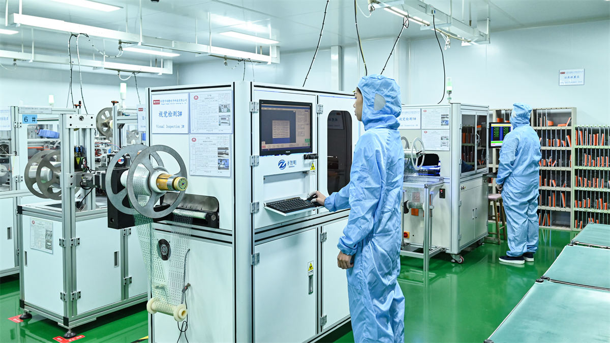
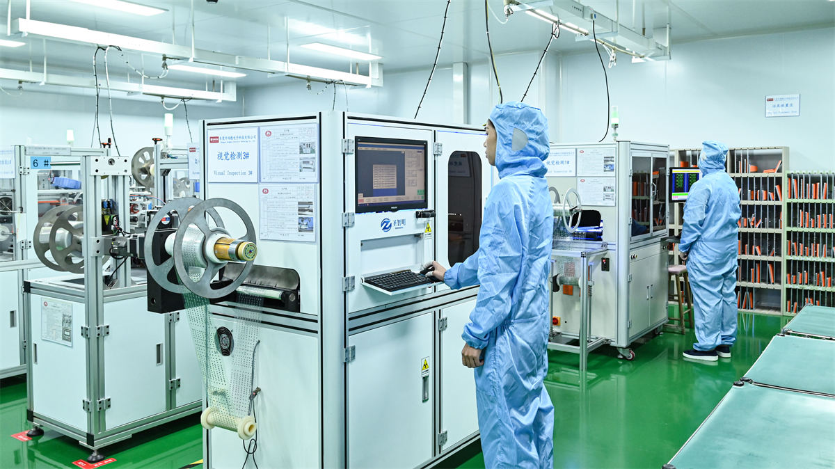
CCD visual inspection instrument checking 4 leg cross metal dome geometry at Dongguan Cevra Electronic Technology Co., Ltd.

CCD Optical Dimensional Check

Visual inspection instrument verifying dome leg contour and dimple centration

Apex Dimple Concentricity Scan

Precision Tension Tester measuring adhesive peel force on metal dome array carriers

Adhesive Carrier Peel Tester

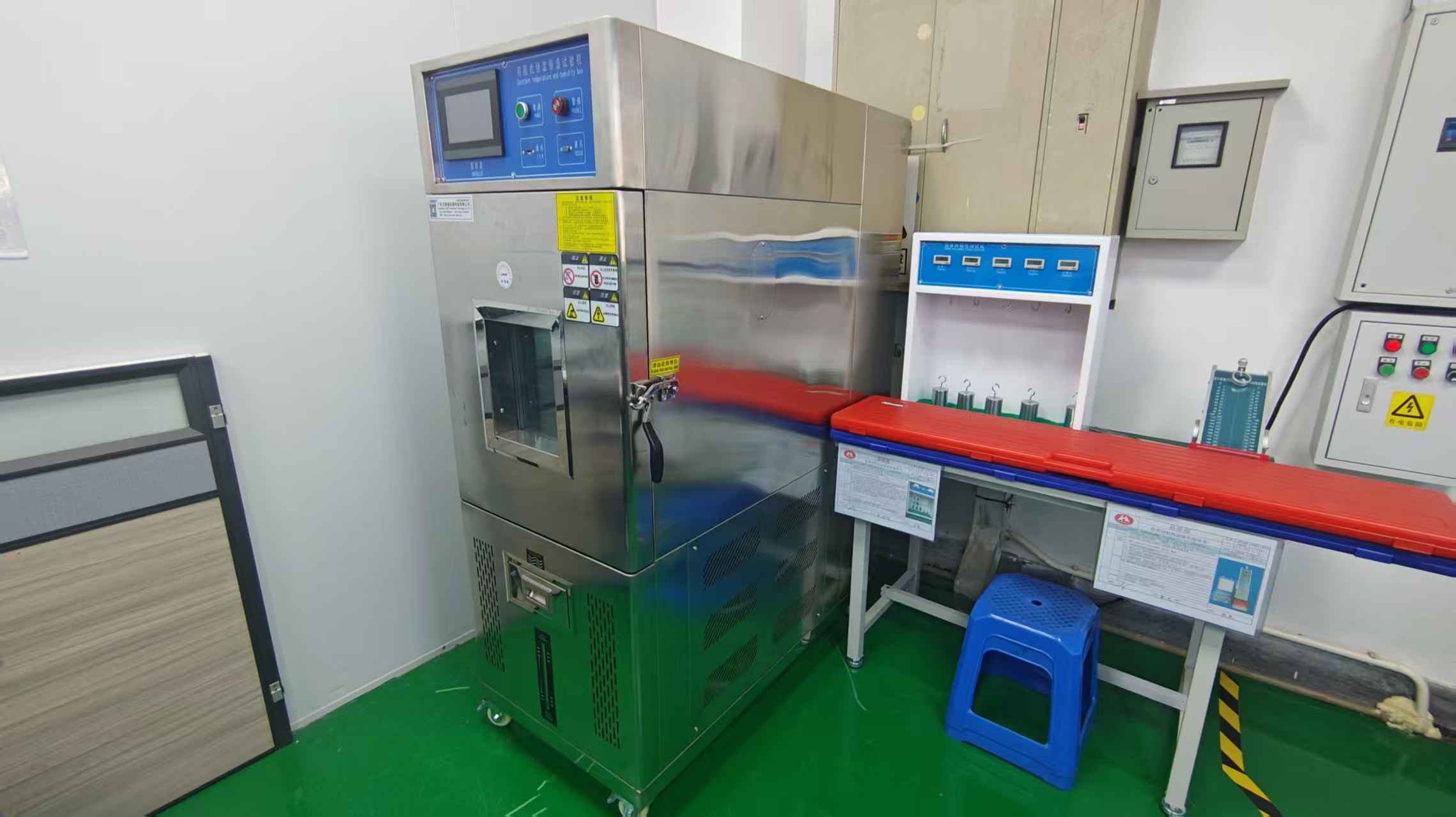
High and low temperature test cabinet evaluating dome fatigue in thermal extremes

Thermal Cycle Stability Chamber

Tactile Architecture 4 Leg Cross Shaped Dome Circular (Round) Snap Dome Triangular Tactile Dome Elastomeric Rubber Carbon Pill
Tactile Ratio (Snap Feel) Exceptional (45% – 68%) Moderate (20% – 35%) Sharp / Very High (50% – 70%) Soft / Dampened (15% – 30%)
PCB Routing Underneath Permits dense traces between legs Blocks trace routing (needs vias) Limited trace space between corners Requires wide dual-interdigital tracks
Actuation Force Range 160gf to 500gf (Custom up to 800gf) 100gf to 350gf 180gf to 450gf 50gf to 200gf
Travel Distance 0.30mm – 0.65mm 0.15mm – 0.35mm 0.25mm – 0.45mm 0.80mm – 1.50mm
Mechanical Operating Life 1,000,000 to 5,000,000 cycles 500,000 to 2,000,000 cycles 500,000 to 3,000,000 cycles 500,000 to 1,000,000 cycles
Recommended Footprints Automotive, Medical, Rugged Handhelds Ultra-thin calculators, wearables Space-constrained side buttons Remote controls, consumer keypads
Specification Directory

Curated 4-Leg Cross Metal Dome Configurations

Engineered by Dongguan Cevra Electronic Technology Co., Ltd. for seamless deployment into rigid PCBs, flexible printed circuits (FPC), and membrane switch assemblies.

High speed progressive die stamping of 8.4mm four legged cross tactile domes MOST SPECIFIED

Standard 8.4mm 4-Leg Cross Dome with Dimple

Optimized for automotive dash clusters, industrial handheld pendants, and high-frequency membrane switches requiring clear tactile separation.

  • Diameter8.4 mm
  • Trip Force220gf / 280gf / 350gf
  • PlatingNickel (Ni) or Gold (Au)
  • Contact Resistance< 0.1 Ω (Gold) / < 1.0 Ω (Ni)
  • Travel Distance0.45 mm ± 0.05 mm
  • PackagingBulk / Reel / Array Sheet
Laser cut precision tooling and stamping for 10mm and 12mm cross shaped metal domes DEEP TRAVEL

10.0mm & 12.0mm High-Travel Cross Snap Dome

Engineered specifically for rugged defense computers, outdoor surveying hardware, and medical ventilators where gloves prevent light-touch detection.

  • Diameter10.0 mm / 12.0 mm
  • Trip Force300gf / 380gf / 450gf
  • Base MetalSUS301 High-Yield Steel
  • Dimple GeometrySingle Center or 4-Dimple Leg
  • Travel Distance0.55 mm – 0.65 mm
  • Rated Lifespan> 2,000,000 Cycles
Automated assembly of custom multi-position metal dome array sheets FAST SMT / ARRAY

Custom Multi-Point 4-Leg Cross Dome Array

Pre-spaced cross domes mounted onto high-bond polyester tape with integrated air-escape vent channels for instantaneous one-step chassis assembly.

  • ConfigurationCustom Matrix / Multi-Axis
  • Carrier Tape0.05mm PET + 3M 467MP / 9448A
  • Venting SystemChannelized Internal Venting
  • AlignmentLaser-cut CCD Pin Locators
  • Pitch CenterDown to 8.5 mm Key Center
  • Dust/MoistureIP65 / IP67 Compatible

Metallurgical Selection: Bare vs. Nickel Plated vs. Gold Plated Domes

Selecting the appropriate surface plating determines electrical longevity and resistance to fretting corrosion in high-vibration applications. Our metallurgy engineers at Dongguan Cevra Electronic Technology Co., Ltd. recommend plating specifications based on operating environment and circuit chemistry:

Bare Stainless Steel (SUS)

Unplated passivated high-carbon stainless steel.

  • • Lowest unit BOM cost
  • • Contact resistance: < 3.0 Ω
  • • Ideal for consumer toys & low-humidity indoor circuits
  • • Best used with silver-printed flexible carbon pads
Nickel Plating (Ni: 1.0–2.5µm)

Electroless or electrolytic nickel barrier layer.

  • • Superior abrasion and micro-fretting resistance
  • • Contact resistance: < 1.0 Ω
  • • Prevents oxidation during extended storage
  • • Industrial default for automotive switches & appliance HMIs
Gold Plating (Au: 0.05–0.2µm / Ni)

Hard gold flash over electrolytic nickel substrate.

  • • Ultra-low stable resistance: < 0.1 Ω
  • • Impervious to sulfur, nitric acid & salt fog
  • • Zero contact bounce under micro-ampere logic gates
  • • Mandated for intensive care medical & avionics controllers
Manufacturing Authority

Precision Fabrication at Dongguan Cevra Electronic Technology Co., Ltd.

Operating a vertically integrated 2,600㎡ facility in Dongguan, China with in-house stamping, tooling design, clean-room printing, and lab-grade testing.

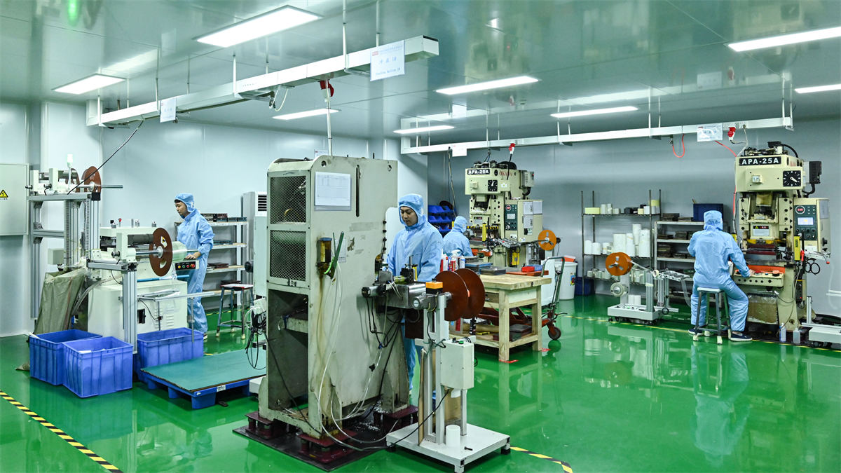
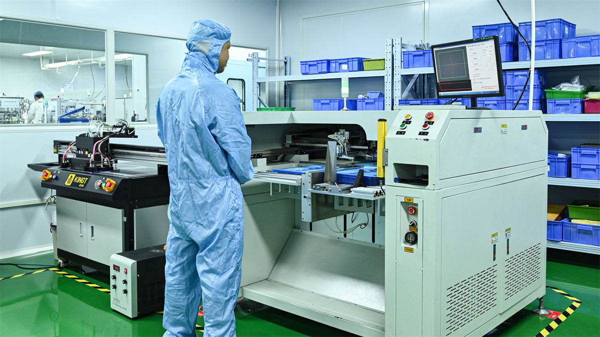
High speed precision punching machine for 4 leg cross metal dome stamping at Cevra factory

High-Speed Punching

Multi-ton micro-gap precision punching machines deliver Burr-free leg contours and consistent dimple depth tolerances (±0.02mm).

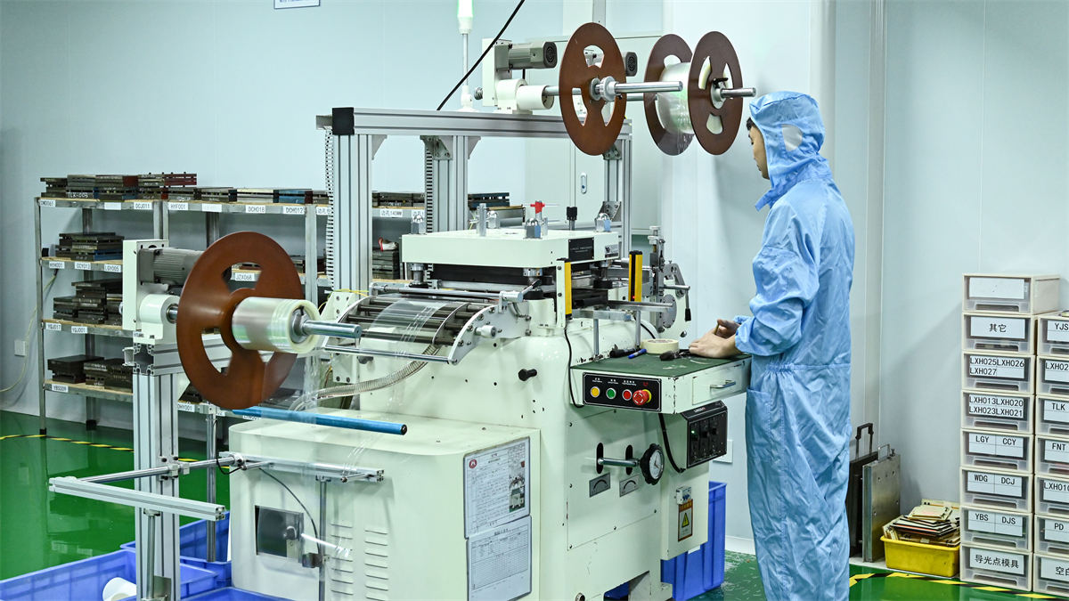
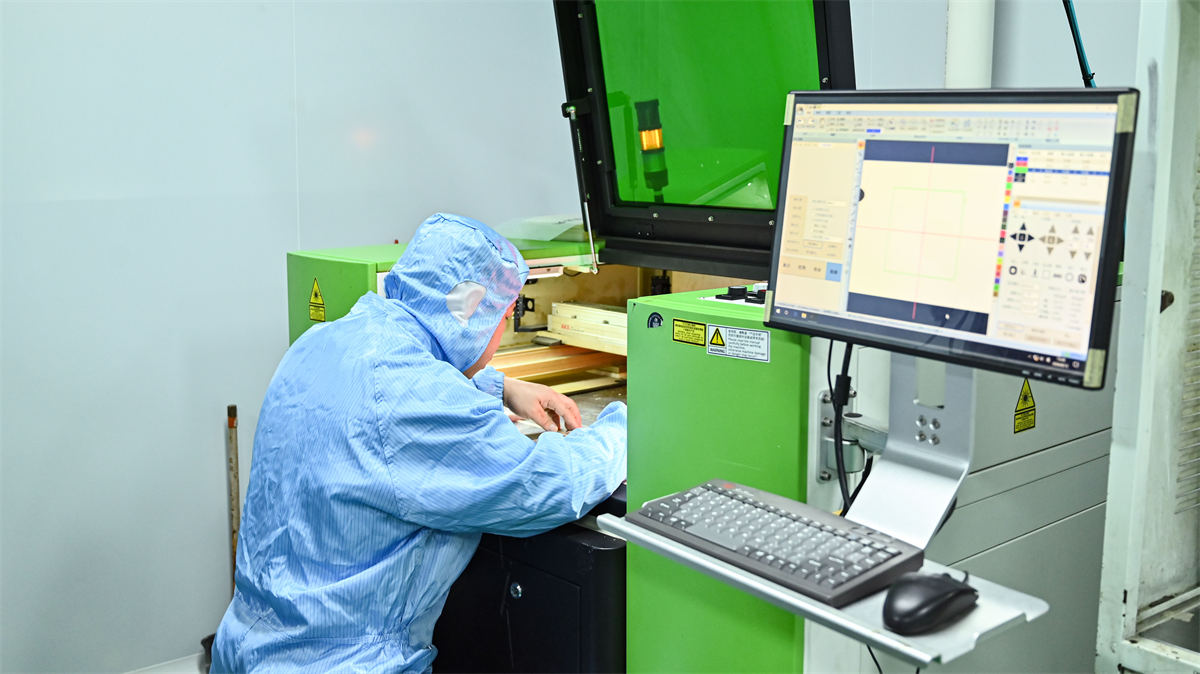
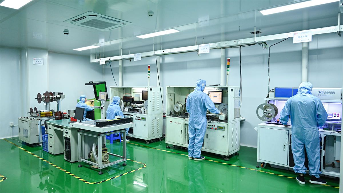
Laser cutting machine creating intricate adhesive spacer vent channels at Cevra

Precision Laser Cutting

Non-contact industrial laser cutting systems formulate complex air venting ducts, spacer cavities, and custom array perimeters without tool wear.

CCD automated camera drilling machine for guide hole registration at Cevra

CCD Vision Drilling

Optical camera-guided drilling machines drill registration locators with 10-micron positional accuracy for flawless PCB mating.

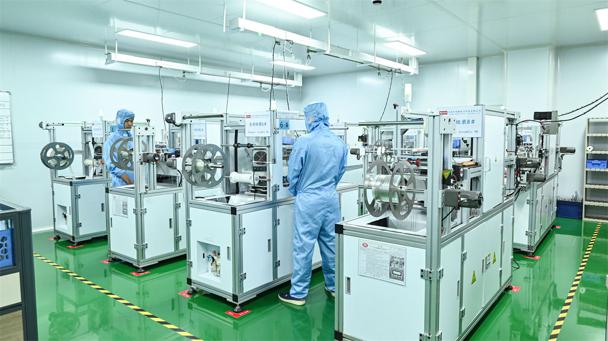
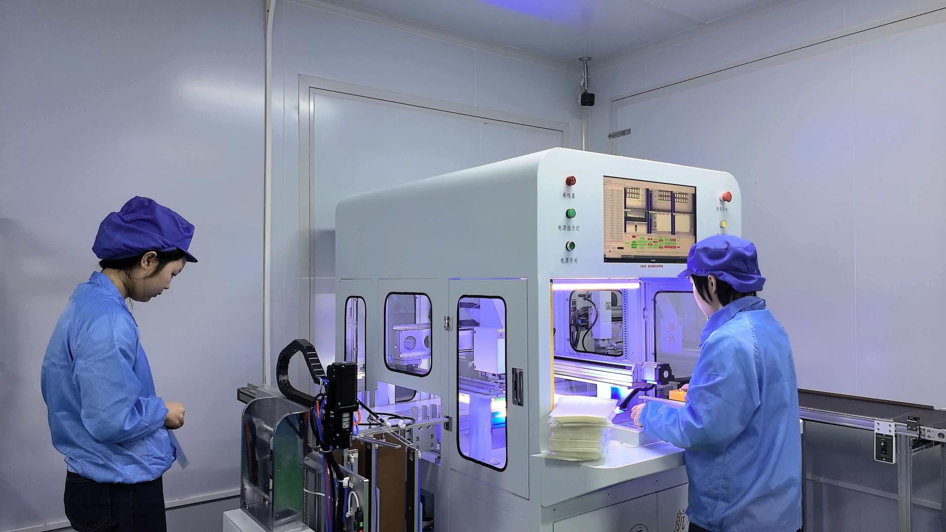
Fully automatic laminating machine integrating carrier adhesives and dome arrays

Automatic Laminating

Continuous bubble-free laminating machinery binds technical adhesives (3M, Nitto, Crown) to silicone/polyester carrier films under clean-room conditions.

Why Global OEMs Audit & Trust Cevra

Founded in March 2009 in Dongguan's manufacturing hub, Dongguan Cevra Electronic Technology Co., Ltd. has spent over 16 years perfecting tactile switch and human-machine interface components. Rather than functioning as an unverified broker or trading desk, our entire production cycle is housed under our certified ISO 9001 quality infrastructure.

From the initial DFM artwork and finite element mechanical simulation in our Design Department to final lot inspection using Fragment Load Testers, Electric Pencil Hardness Testers, Holding Tack Testers, and High & Low Temperature Chambers, every dome lot is fully traceable back to raw steel master coil certs.

16+
Years Stamping Experience
2,600㎡
In-House Manufacturing Area
SGS
Onsite Factory Audited
±0.02mm
Tooling Stamping Tolerance
Engineer-to-Engineer

Frequently Asked Questions: 4 Leg Cross Shaped Metal Domes

Comprehensive, mathematically and mechanically verified answers to the top queries submitted by electronics design engineers and international procurement officers.

What is a 4 leg cross shaped metal dome and why is it preferred over round domes?

A 4 leg cross shaped metal dome (often called a cross tactile snap disc or 4-legged tactile dome) is a momentary electrical contact switch stamped from stainless spring steel featuring four cantilevered symmetrical feet radiating from a raised central spherical crown.

Engineers prefer the 4-leg cross shape over traditional round or circular domes for three distinct reasons:
1. PCB Routing Freedom: The gaps between the four legs permit electrical traces to pass directly through the switch footprint on a single PCB layer. Circular domes cover the entire perimeter, necessitating expensive buried vias or multi-layer boards.
2. Extended Travel & Crisp Tactile Snap: The four legs allow deeper downward deflection (up to 0.65mm) and a higher tactile ratio (TR 45%–68%), yielding an unmistakable mechanical click feeling.
3. Self-Centering & Non-Teetering: The wide four-point stance provides exceptional stability under off-center actuation, dramatically reducing the risk of edge-jamming or premature switch fatigue.

What actuation forces and travel distances are standard for 4-leg cross domes?

Standard nominal actuation forces range from 160gf to 500gf, with custom configurations engineered up to 800gf for high-vibration off-highway vehicles. The most prevalent specifications across industrial electronics are 220gf, 280gf, and 350gf.

Actuation travel distances scale with dome diameter:
• 6.0mm Cross Domes: 0.25mm – 0.35mm travel (ideal for compact medical pagers).
• 8.4mm Cross Domes: 0.35mm – 0.48mm travel (the industry standard for membrane switches and steering wheel controls).
• 10.0mm & 12.0mm Cross Domes: 0.45mm – 0.60mm travel (deep-travel ergonomics for industrial controllers).
• 14.0mm+ Cross Domes: 0.55mm – 0.70mm travel (heavy outdoor keypads and tactile push-buttons).

How should PCB landing contact pads be designed for 4-leg cross domes?

To achieve reliable contact resistance and prevent intermittent open circuits over a multi-million-cycle lifespan, PCB layout designers should adhere to the following pad geometry guidelines:

• Center Contact Pad: A solid circular pad positioned concentric to the dome apex. For an 8.4mm dome, a center pad diameter of 1.5mm to 2.0mm is optimal.
• Outer Ring / Footprint Pads: Either a continuous circular ring or four discrete landing pads spaced at 90-degree intervals matching the leg touchdown radius. The clearance gap between the center pad and the outer contact trace should be at least 0.5mm to 1.0mm to eliminate micro-bridging.
• Plating Matching: If the metal dome is nickel-plated, specify ENIG (Electroless Nickel Immersion Gold) or Hard Gold on the PCB landing pads. Mismatched bare copper will oxidize rapidly, driving contact resistance from <1Ω to >100Ω.

Why is air venting critical in 4-leg cross metal dome arrays and switch assemblies?

When an operator presses a metal dome, the internal chamber volume decreases within a fraction of a millisecond. If this air has no escape route:

1. Mushy Tactility: The trapped pneumatic cushion resists collapse, degrading the tactile snap and dropping tactile ratio by up to 50%.
2. Contact Bounce & Sluggish Return: Trapped vacuum beneath the dome during the return stroke inhibits snappy rebound, causing erratic electrical debouncing intervals.
3. Adhesive Delamination: High-frequency cycling pumps air pressure into the adhesive boundary, eventually lifting the carrier film away from the PCB.

Dongguan Cevra Electronic Technology Co., Ltd. resolves this by laser-cutting micro-vent channels into the intermediate spacer adhesive, interconnecting all switch cavities to an internal equalization reservoir or PCB breather hole.

How does the actuator / plunger design affect dome operating life?

The interface between the external actuator (plunger) and the metal dome apex is critical. Key design rules include:
• Contact Area: The actuator plunger tip should cover between 30% and 50% of the dome's diameter. A pointed tip creates localized stress concentration that permanently dents the apex, shortening life to under 100k cycles. A plunger that is too broad rests on the legs and deadens the snap.
• Hardness: Use rigid or semi-rigid materials (such as Shore D polyurethane, polyoxymethylene, or hard silicone 60–70 Shore A).
• Dimple Synergy: For completely flat membrane overlays, choose a 4 leg cross dome with an engineered center dimple. The dimple acts as an integrated internal plunger, transferring perpendicular force directly to the buckling apex.

What is the difference between loose domes, dome arrays, and tape & reel packaging?

Dongguan Cevra Electronic Technology Co., Ltd. provides three distinct packaging methodologies tailored to procurement volumes and assembly automation:

1. Loose Domes (Bulk): Cost-effective for low-volume repairs, prototyping, or hand-placement with suction pens. Packaged in anti-static jars or bags (MOQ: 1,000 pcs).
2. Custom Metal Dome Arrays (Peel-and-Place Sheets): Domes are factory-placed onto custom pre-spaced adhesive sheets with integrated air channels. Operators peel the entire multi-key array and mount it on the PCB in seconds with alignment pins (MOQ: 100 sheets).
3. SMT Tape and Reel (Carrier Tape): Domes are oriented individually into standard embossed carrier pockets (EIA-481 compliant) covered by heat-sealed peelable top tape. Standard SMT pick-and-place feeders lift and mount domes directly onto SMT solder pads or solder-less PCB contact matrices (MOQ: 5,000 pcs / reel).

Direct Factory Engineering Engagement

Request Engineering Samples & DFM Quotation for 4 Leg Cross Metal Domes

Whether you are prototyping a next-generation surgical device console, refining automotive steering wheel haptics, or sourcing high-volume tape-and-reel arrays for automated SMT lines, Dongguan Cevra Electronic Technology Co., Ltd. provides prototype samples, custom force variations, and direct engineering consultations within 24 hours.

Free Sample Kits Available
Rapid 5–7 Day Prototyping
Mutual NDA Protected